Newsletter Subscribe
Enter your email address below and subscribe to our newsletter

 ByJohn A
Underground electrical distribution is widely used in residential developments, commercial properties, industrial facilities, and infrastructure projects where reliable power delivery and an organised site layout are important. Unlike overhead distribution systems, underground networks place electrical cables below ground, helping reduce visual clutter and limiting exposure to certain weather-related hazards. However, these systems require careful planning to ensure electrical safety, accessibility, reliable operation, and long-term maintainability.
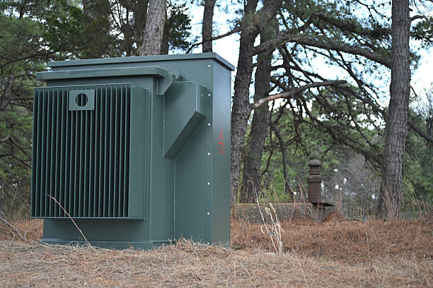
Three-phase pad-mounted transformers play an important role in these installations. Positioned on ground-level concrete pads or approved foundations, a 3 phase pad mounted transformer transfers electrical energy between distribution voltage levels and supplies power to downstream circuits. Its enclosed construction makes it suitable for many outdoor applications when the equipment is correctly specified and installed.
Planning underground electrical distribution with 3 phase pad mounted transformers involves more than selecting a transformer with the correct capacity. Engineers must consider electrical demand, voltage requirements, cable routing, site conditions, protective devices, access arrangements, and future expansion.
This article explains the key considerations involved in designing an underground distribution system around three-phase pad-mounted transformers.
A three-phase pad-mounted transformer is an electrical distribution unit designed to serve three-phase loads or supply a suitable distribution network. It typically contains a magnetic core, primary and secondary windings, insulation, terminals, and protective components within a secure enclosure.
The transformer is installed at ground level on a suitable foundation, allowing underground cables to enter and leave through designated compartments. Depending on the application, it may be used to step down medium-voltage distribution electricity to a lower voltage suitable for buildings, equipment, and local distribution circuits.
Pad-mounted transformers are useful for underground networks because their configuration supports below-ground cable connections while keeping the transformer accessible for authorised inspection and maintenance.
Common applications include:
The appropriate transformer design depends on the electrical utility’s requirements, site conditions, load characteristics, and applicable electrical standards.
Three-phase electrical systems use three alternating voltages that are separated by 120 electrical degrees. This arrangement supports efficient power transmission and is particularly useful for motors, industrial machinery, HVAC equipment, and larger commercial loads.
A three-phase pad-mounted transformer can provide a suitable secondary voltage for connected equipment, depending on its winding configuration and nameplate specifications. Common configurations include delta and wye connections, each offering different characteristics for voltage relationships, grounding, and load distribution.
The required configuration must be established during the design stage. It should match the utility supply, connected equipment, grounding arrangement, and relevant electrical requirements.
Accurate load assessment is one of the most important stages in underground distribution planning. An incorrectly sized transformer can result in inadequate capacity, unnecessary expenditure, poor operating efficiency, or difficulties accommodating future demand.
Start by identifying the equipment, buildings, and circuits that the transformer will supply. This may include lighting, receptacles, heating and cooling systems, lifts, pumps, machinery, and other electrical loads.
The assessment should distinguish between connected load and expected maximum demand. Not every item of equipment operates simultaneously, so realistic demand calculations can help determine the required transformer capacity without relying solely on the sum of every nameplate rating.
Engineers should also account for motor starting currents, nonlinear electronic loads, power factor, load diversity, and anticipated operating schedules where relevant.
For a balanced three-phase load, apparent power can be calculated using:
[
S=\frac{\sqrt{3}\times V_L\times I_L}{1000}
]
Where:
For example, a balanced load drawing 100 A at 400 V requires approximately 69.3 kVA of apparent power. This calculation helps estimate demand, but transformer selection must also account for actual operating conditions and applicable design requirements.
Underground distribution infrastructure can be expensive to modify after roads, landscaping, parking areas, and buildings have been completed. Transformer capacity and cable routes should therefore be evaluated against realistic future development plans.
Consider whether the site may add new buildings, electric vehicle charging, additional HVAC equipment, production machinery, or other significant loads. Future demand should be estimated using a documented engineering assessment rather than an arbitrary oversizing allowance.
The design should balance anticipated growth with equipment utilisation, installation cost, utility requirements, and available space.
The cable network connects the utility supply to the transformer and distributes power from the transformer to downstream loads. Its layout affects installation costs, electrical performance, maintenance access, and the risk of accidental damage.
Cable routes should be planned around site boundaries, buildings, roads, drainage systems, other utilities, and existing underground infrastructure. A route that appears straightforward on a drawing may be unsuitable if it conflicts with foundations, water pipes, communication cables, or future construction.
Designers should review current utility records and arrange appropriate site surveys before excavation. Where necessary, underground services should be located and verified using suitable detection methods.
Cable routes should also account for changes in direction, pulling requirements, access points, and any restrictions imposed by the cable manufacturer or utility provider.
Cable sizing must consider more than the rated current. Engineers should evaluate:
Cables may be installed in approved ducts, conduits, or direct-buried arrangements, depending on the project design and local requirements. Each method has different implications for installation, mechanical protection, heat dissipation, and future cable replacement.
Cable ratings should be verified for the actual installation conditions. A conductor that is adequate in one environment may require a larger size when installed alongside other cables or in soil with limited thermal performance.
Underground electrical cables often share developed sites with water, gas, telecommunications, drainage, and other infrastructure. Their relative positions and separation distances must comply with applicable utility requirements and local regulations.
Clear documentation of cable routes, depths, crossings, and access points helps reduce the risk of damage during future excavation. As-built drawings should be updated after installation so maintenance teams can identify buried infrastructure accurately.
The location of a three-phase pad-mounted transformer affects safety, maintenance access, cable installation, and the overall layout of the underground distribution network.
The transformer foundation must provide stable support for the equipment and accommodate the loads imposed by the transformer and its installation. Ground conditions should be assessed to determine whether soil preparation, reinforcement, or other foundation measures are necessary.
Drainage is equally important. The site should be arranged to prevent water from collecting around the foundation or entering cable compartments. Flood-prone locations may require additional engineering measures or an alternative installation position.
The foundation dimensions, cable entry openings, anchoring arrangements, and finished ground level should follow the approved transformer drawings and utility requirements.
Transformers need sufficient clearance for authorised personnel to open compartments, operate approved equipment, inspect components, and carry out maintenance. The required working space depends on the equipment design and local utility standards.
Avoid placing the transformer where doors would be obstructed by fences, walls, parked vehicles, landscaping, or other equipment. Access for lifting and replacement should also be considered during site planning.
Where vehicles or mobile equipment could strike the transformer, suitable protective barriers may be necessary. Their placement should preserve the required access and working clearances rather than create new obstructions.
Protection and grounding are essential parts of an underground electrical distribution design. They help manage electrical faults, reduce hazards, and support safe operation of the connected network.
The transformer specification should identify the required primary and secondary protection, switching arrangements, and fault-current ratings. Depending on the network design, the installation may incorporate fuses, circuit breakers, surge protection, and approved switching equipment.
Protection must be coordinated with the utility supply and downstream distribution equipment. Engineers should evaluate available fault current, transformer impedance, conductor ratings, and the operating characteristics of protective devices.
Incorrectly coordinated protection can cause unnecessary outages or fail to isolate a fault as intended. Final selections and settings should therefore be verified by qualified electrical professionals.
Grounding arrangements depend on the transformer winding configuration, system voltage, neutral requirements, and local electrical regulations.
The design should address the transformer enclosure, grounding electrodes where required, neutral connections, and the bonding of associated metallic components. Engineers must assess ground-fault conditions and ensure that the installation complies with the applicable safety requirements.
Grounding conductors and connections should be installed according to approved drawings and verified during commissioning.
A well-designed underground distribution system should remain accessible throughout its service life. Although cables are buried, the transformer itself requires periodic inspection and may eventually need repair or replacement.
Project documentation should include transformer ratings, voltage configurations, cable sizes, routes, protective device details, grounding arrangements, and relevant test results.
As-built drawings should reflect the actual installation rather than only the original design. This information helps maintenance teams locate cables, identify equipment, and plan future modifications without unnecessary excavation.
If the site is expected to expand, engineers should review whether additional transformer capacity, feeder routes, or distribution equipment may be required. Spare duct capacity may be useful where permitted by the design and utility specifications.
However, spare ducts and future cable provisions must remain within the transformer manufacturer’s and utility’s limits. The design should also preserve access for maintenance vehicles and equipment throughout the expected service life.
Before an underground distribution system is placed into service, the installation should undergo the inspections and tests required by the project specification, utility, manufacturer, and applicable standards.
Typical commissioning activities may include:
Testing must be performed by appropriately qualified personnel using approved procedures. Medium-voltage cables and transformer terminals can present lethal hazards, so energisation must not proceed until the required safety checks and approvals have been completed.
Planning underground electrical distribution with 3 phase pad mounted transformers requires a coordinated approach to electrical design, site preparation, cable routing, transformer selection, protection, grounding, and long-term maintenance. Each decision influences how reliably the distribution network will operate and how easily it can be inspected, repaired, or expanded.
A successful project begins with an accurate assessment of electrical demand and continues with appropriate cable sizing, suitable transformer placement, effective drainage, adequate working clearances, and properly coordinated protective devices. Utility requirements and applicable electrical standards should guide the design from the initial planning stage through installation and commissioning.
Meta Power Solutions recognises the importance of careful transformer planning and proper equipment selection in supporting reliable electrical distribution. By addressing these considerations early, engineers and project owners can develop an underground distribution system that supports dependable power delivery, makes effective use of available space, and remains practical to maintain as site requirements evolve.